(Mis)adventures in getting a working display on mainline Linux
or, how I spent nearly 3 weeks trying to figure out why I wasn't getting an image on my Galaxy Tab 3 8.0.
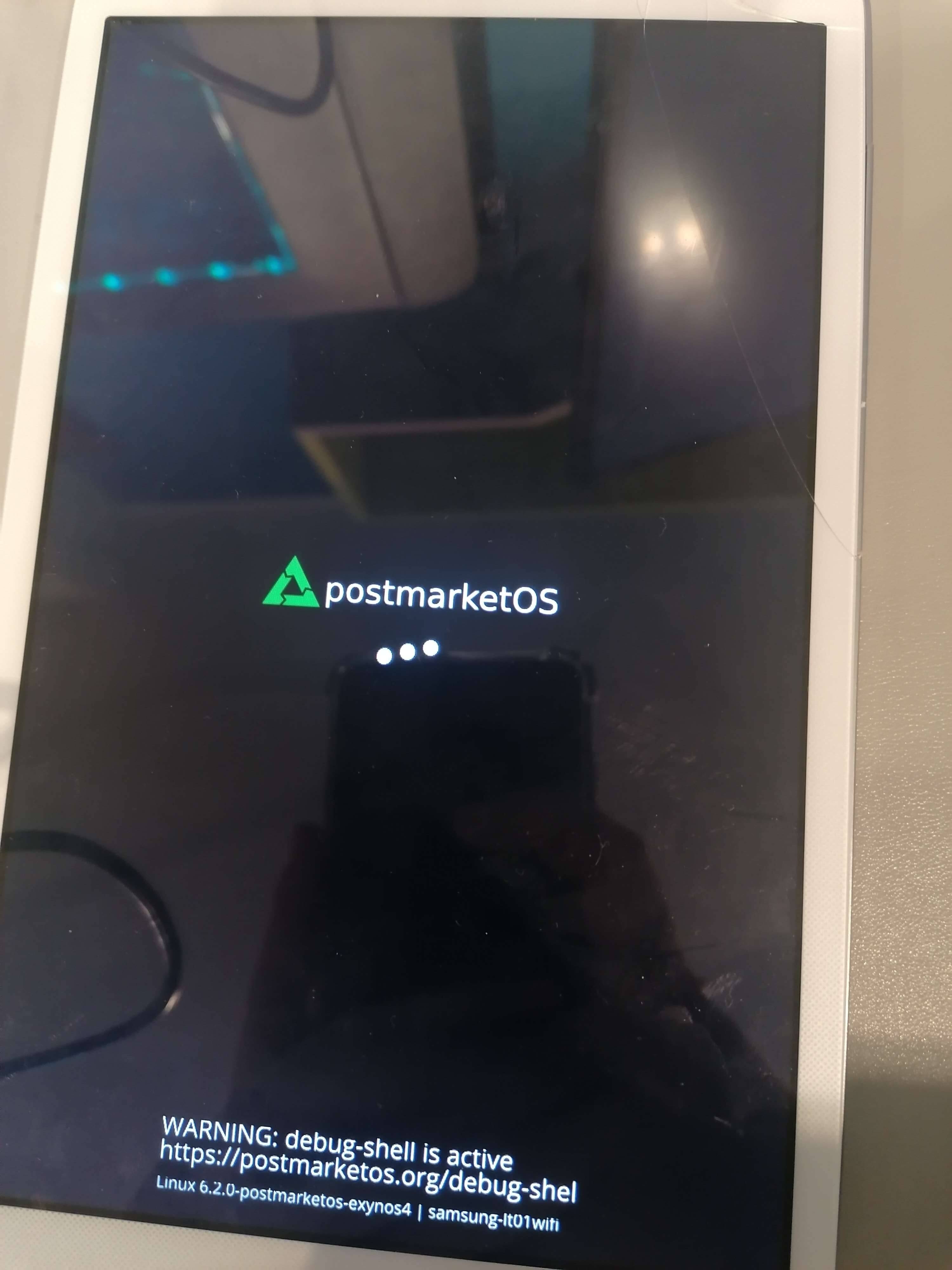
A while back, I tried to mainline my Samsung Galaxy Tab 3 8.0 (lt01). It’s a tablet from 2013 with the Exynos 4212 chipset - the dual-core variant of the already well-supported Exynos 4412. When support for the Exynos 4 mainline kernel was added to postmarketOS, I figured it was the perfect time to try and get it running on mainline.
The initial task was re-introducing support for the Exynos 4212, as it was dropped a few years back. This was fairly straightforward - just moving some things into a separate .dtsi and modifying some drivers was enough to get it booting. Unfortunately, I hit a pretty big hurdle very quickly - the moment I booted into mainline, the display would completely shut off.
I wanted to figure this out quick, because the kernel moves fast, and I didn’t feel like rebasing the Exynos 4212 patches forever. But I wasn’t just going to try to merge a tablet without a working screeen into mainline!
And so began a multiple week journey, as I tried to figure out the entire problem one step at a time.
Overview
The average phone/tablet screen comprises of three “layers”:
- The touchscreen/digitizer, which handles touch inputs; sometimes this also includes touchkeys (menu/back buttons next to the home button, from ye old times when phones still had physical buttons);
- The display panel/LCD, which is what displays the image;
- The backlight, which controls the panel’s brightness.
In some cases, the display panel handles the backlight itself. However, in the case of the Galaxy Tab 3 8.0, they are handled separately. The Galaxy Tab 3 8.0 uses an LSL080AL02 panel1 managed by the S6D7AA0 IC, and a separate backlight controller - the TI LP8556TMX.
The panel isn’t supported in mainline, but the MSM8916 kernel fork has a driver for a very similar panel, used in the Samsung Galaxy Tab A 8.0 2015, which I used as a base for my driver. The LP8556 chip, however, is supported as part of the lp855x driver.
After adding the driver for the backlight controller into the DTSI, however, nothing seemed to change. Adding the panel driver didn’t seem to fix anything either (but we’ll talk about that later). I also thought that maybe the touchscreen or the HDMI output/MHL are related, but enabling the drivers for these didn’t change anything either.
So, the next logical step was to open up the device and see if we can spot anything obvious in there.
A quick look at the service manual reveals some helpful hints for figuring out why the display isn’t working. It also shows the schematics for two chips and the display connector:
- The chip marked as U602 is the LP8556 chip. It outputs a 19V signal going directly to the connector. It’s connected to two supplies: V_BATT (an always-on 5v line) for the VDD, and a line managed by the LED_BACKLIGHT_RESET GPIO pin for the EN/VDDIO.
- The chip marked as U600 seems to be some kind of signal booster as well, outputing a 3.3v signal that goes to the display connector. It’s enabled by setting the LCD_EN pin signal to high.
- Finally, the connector itself - this has a few standard MIPI connection lines, a connection to the 19V signal from the LP8556, the 3.3V signal from the booster and VMIPI_1.8V from the PMIC. It’s also connected to an interrupt line, and the 3 LED output pins from the LP8556 chip are connected to it as well.
I went through the troubleshooting steps and quickly found the culprit - the 19V line from the LP8556 chip was, in fact, at 14.35V. I verified that the correct voltage, as seen when booting into the recovery (downstream kernel) was about 19.32V. Nearly 5V missing - strange…
Figuring out the backlight
But wait - 3 LED output pins? 19V signal? What is any of this about? Ah, if only we had the datasheet for the LP8556…
…well, turns out, we do! TI was kind enough to make the datasheet for this chip publically available.
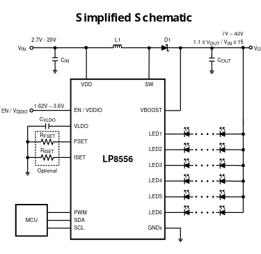
The LP8556 is described as a “High-Efficiency LED Backlight Driver For Tablets”. The brightness is controlled by a PWM signal from 25 to 75 kHz. It also has various configuration options which can be set through an I2C interface.
The pin functions are explained on page 5 of the datasheet. The important parts are as follows:
- VDD is the power supply.
- EN/VDDIO is both the chip enable and the power supply reference for the PWM, SDA and SCL pins.
- PWM is the input PWM signal.
- Pins LED1 through LED6 are LED drivers.
- VBOOST is the boosted output voltage.
In the downstream kernel, the parameters for the backlight are defined at the very end of the arch/arm/mach-exynos/board-lcd-mipi.c file.
static struct lp855x_platform_data lp8856_bl_pdata = {
	.mode		= PWM_BASED,
	.device_control	= DEVICE_CONTROL_VAL,
	.initial_brightness = 120,
	.load_new_rom_data = 1,
	.size_program	= ARRAY_SIZE(lp8556_eprom_arr),
	.rom_data	= lp8556_eprom_arr,
	.use_gpio_en	= 1,
	.gpio_en	= GPIO_LED_BACKLIGHT_RESET,
	.power_on_udelay = 1000,
};
There are two structs for the I2C configuration data: one for 4 drivers, and one for 3 drivers.
static struct lp855x_rom_data lp8556_eprom_arr[] = {
	{EPROM_CFG3_ADDR, 0x5E, 0x00},
   ...
};

static struct lp855x_rom_data lp8556_eprom_3drv_arr[] = {
	{EPROM_CFG3_ADDR, 0x5E, 0x00},
   ...
};
As we’ve already estabilished by looking at the service manual, we only use 3 drivers. This is also confirmed by the check in lcd_bl_init, which checks for the lcdtype variable:
static int lcd_bl_init(void)
{
#ifdef CONFIG_FB_S5P_S6D7AA0
	if (0x800 == (lcdtype & 0xff00)) {
		lp8856_bl_pdata.rom_data = lp8556_eprom_3drv_arr;
		lp8856_bl_pdata.size_program = ARRAY_SIZE(lp8556_eprom_3drv_arr);
	}
#endif

   ...
}
lcdtype is taken from the cmdline parameters, and on my tablet it was set to 2049. Sure enough, the if condition is met, and the 3 driver configuration options are selected.
Three other things to take note of here are:
modein the platform data takes two options:REGISTER_BASEDorPWM_BASED. Here, it’s set toPWM_BASED.device_controlis a device-specific value. Ours is defined in the driver as(PWM_CONFIG(LP8556) | 0x80), which ends up evaluating as 0x80. (PWM_CONFIG(LP8556)evaluates toLP8556_PWM_CONFIGwhich in turn evaluates toLP8556_PWM_ONLYfrom thelp8556_brightness_sourceenum, and equals 0.)- The
gpio_envalue is, indeed, set to the LED_BACKLIGHT_RESET GPIO.
This seems like enough information to give to the mainline driver, right? Well, not quite.
See, to actually be able to enable PWM mode in the mainline driver, we needed two important pieces of information:
- The PWM device to use. This was simple enough to figure out -
GPIO_LED_BACKLIGHT_PWMinarch/arm/mach-exynos/include/mach/gpio-rev00-tab3.his defined asGPD0(1), which corresponds to PWM 1. - The PWM period. This one, however, wasn’t anywhere near the lp855x driver.
I went through quite a lot of debugging to figure this part out. Here are some of the more interesting discoveries I made along the way:
- In downstream, two backlight devices appeared under
/sys/class. One was thelp855xdevice, but it seemed to do nothing… the other was anmdniedevice, that actually changed the brightness…? It’s controlled by the driver atdrivers/video/samsung/mdnie.c, which is the driver for mDNIe - “Mobile Digital Natural Image Engine”, a Samsung-proprietary color correction system. - At some point while digging through the kernel for clues, I found
arch/arm/plat-samsung/dev-backlight.c, which seemed to contain the PWM period value I was looking for -78770. - I copied the period and set up PWM just like the mainline
lp855xdriver docs told me to… but I still got nothing.
Figuring out the backlight failures
This part was added later, on April 15th 2023. As it turns out, I had jumped to conclusions here way too fast, and missed some details.
Indeed, the downstream lp855x device isn’t fully configured for PWM control - the folks adding the necessary setup structs did not set up the pwm_set_intensity element, which should be a pointer to a function that sets the duty cycle for the PWM to match the requested brightness. Let me explain.
The PWM period is the total period of the PWM signal, and the duty cycle is the active time. The way you set the backlight’s intensity is by adjusting the duty cycle value - the closer it is to 0, the dimmer the backlight gets, and the closer it is to the period (which acts as the “maximum” value), the brighter it gets.
When trying to figure this out, I stumbled across two issues:
Firstly, I didn’t actually add the PWMs correctly! Turns out, I accidentally added a pwm property instead of the pwms property. In my defense, the driver doesn’t even print an error message when this happens - it just silently fails. I didn’t know this at the time - so I had just assumed that the driver was broken.
I figured out that I could export out the PWM pin using echo "1" > /sys/class/pwm/pwmchip0/export, then set the duty cycle and period values manually following the lp855x driver code that should have worked. To be exact - I figured that I could just set the duty cycle to the period, effectively blasting the backlight at full brightness. And indeed, I saw the voltage rise from 14.25V to about 16V - that’s better, but not quite enough to get it to work just yet!
Since I now knew that PWM controlled the backlight, I decided to use the generic pwm-backlight driver instead. I copied the pwm-backlight node using the generic pwm-backlight driver from another Exynos device, the Galaxy Note 10.1 (p4note):
	backlight: backlight {
		compatible = "pwm-backlight";
		pinctrl-0 = <&backlight_reset>;
		pinctrl-names = "default";
		enable-gpios = <&gpm0 1 GPIO_ACTIVE_HIGH>; /* BACKLIGHT_RESET pin */
		pwms = <&pwm 1 78770 0>;
		brightness-levels = <0 48 128 255>;
		num-interpolated-steps = <8>;
		default-brightness-level = <12>;
	};
For the time being, it worked, and the backlight was now turning on!
However, that wasn’t the end of it. There was a second issue that even the pwm-backlight driver couldn’t fix, and it was the reason for why my initial test with an exported PWM pin didn’t work:
For some reason, setting the brightness to the maximum value, and thus setting the duty cycle to 100%, caused the backlight to behave as if it was set to 0%. That’s right - setting the maximum brightness would cause the backlight to turn off. Not exactly ideal.
I set up the lp855x node, this time correctly, to see if maybe setting the configuration values there would fix it:
	backlight: backlight@2c {
		compatible = "ti,lp8556";
		reg = <0x2c>;
		status = "okay";

		bl-name = "lcd-bl";
		dev-ctrl = /bits/ 8 <0x80>;
		init-brt = /bits/ 8 <0x78>; /* 120 */

		power-supply = <&vbatt_reg>;
		enable-supply = <&backlight_reset_supply>;

		pwms = <&pwm 1 78770 0>;
		pwm-names = "lp8556";
		pwm-period = <78770>;

		rom_a3h {
			rom-addr = /bits/ 8 <0xa3>;
			rom-val = /bits/ 8 <0x5e>;
		};

		rom_a5h {
			rom-addr = /bits/ 8 <0xa5>;
			rom-val = /bits/ 8 <0x34>;
		};

		rom_a7h {
			rom-addr = /bits/ 8 <0xa7>;
			rom-val = /bits/ 8 <0xfa>;
		};
	};
This one indeed worked, and as a bonus, I didn’t have choppy switches between brightness settings anymore - the transition between brightness settings was now smoothed out automatically. It also fixed an issue where setting the brightness to 0 in Phosh completely shut down the display as well. But it did not fix the backlight shutting down at 100%.
I went back to the mdnie driver in downstream, and confirmed that it was indeed doing something with the backlight. However, I could not find any mentions of the PWM interface anywhere - all it seemed to be doing was modifying its own registers. That’s right, this is not a software-only driver, this thing has hardware registers! Now that’s what I call proprietary.
In any case - I haven’t figured out the cause of this problem yet. I suspect it might be related to the mdnie driver, which isn’t implemented in mainline at all. I ended up working around this by modifying the driver to simply never set the duty cycle to 100%, and while that works well enough, it’s very much a hack and would require some proper investigation down the line.
Other than that hurdle, we now had a working backlight!
Figuring out the panel connection
Of course, getting the backlight working was half of the success. The other half was getting anything to display on the screen at all. And currently, that did not seem to be happening.
The display logo would look like there was a grid overlayed on it, and would fade out. Occasionally, there would be a colored line somewhere on the screen, and would fade out equally as quickly. But what was the reason?
FIMD and DSI
While trying to figure this out, I wrote an e-mail to the guy who worked on the p4note, and asked if he had any similar issues when working on the display. He replied with some fairly interesting advice, which I was able to combine with what I saw in the p4note dtsi.
Unfortunately, it turns out that there are two ways to attach a display, depending on the way it’s controlled: directly through the FIMD (usually for LVDS panels), or through the DSI master/DSIM (for, who would’ve guessed, DSI panels). The Note 10.1 used the FIMD method, and the Tab 3 8.0 used DSI. Thus, the advice wasn’t all that useful in my case. But let’s start at the beginning.
In the case of panels connected directly to FIMD (Fully Interactive Mobile Display), the initialization looks a little something like this:
The panel is dunked somewhere into the / node…
/ {
	// [...]
	panel {
		compatible = "samsung,ltl101al01";
		pinctrl-0 = <&lvds_nshdn>;
		pinctrl-names = "default";
		power-supply = <&panel_vdd>;
		enable-gpios = <&gpm0 5 GPIO_ACTIVE_HIGH>;
		backlight = <&backlight>;

		port {
			lcd_ep: endpoint {
				remote-endpoint = <&fimd_ep>;
			};
		};
	};
};
The port node is crucial here - it acts as a way to tell the FIMD node, located a bit lower, about the connected display. Here’s what the FIMD node looks like:
&fimd {
	pinctrl-0 = <&lcd_clk &lcd_data24>;
	pinctrl-names = "default";
	#address-cells = <1>;
	#size-cells = <0>;
	status = "okay";

	samsung,invert-vclk;

	port@3 {
		reg = <3>;

		fimd_ep: endpoint {
			remote-endpoint = <&lcd_ep>;
		};
	};
};
If in doubt, read the manual. The documentation also explains some options I haven’t mentioned here (such as samsung,invert-vclk).
Note: An interesting thing of note here is the
pinctrlsetup. LVDS pannels connected directly to the FIMD will usually be connected through the LCD data pins. You can check this in downstream - check thegpiodefinitions file for your device, and see if the comments mention any LCD data pins of any kind. Hint - the pins you’re looking for are located in the pinctrl definitions inexynos4x12-pinctrl.dtsiin mainline.
As for DSI panels - the documentation for DSIM also mentions a port-based setup, but from what I’ve seen by grepping around the kernel, no DTSIs use it. Instead, the panel is simply dropped directly into the dsi node - here, an example from the galaxy-s3 DTSI:
&dsi_0 {
	vddcore-supply = <&ldo8_reg>;
	vddio-supply = <&ldo10_reg>;
	samsung,burst-clock-frequency = <500000000>;
	samsung,esc-clock-frequency = <20000000>;
	samsung,pll-clock-frequency = <24000000>;
	status = "okay";

	panel@0 {
		compatible = "samsung,s6e8aa0";
		reg = <0>;
		vdd3-supply = <&lcd_vdd3_reg>;
		vci-supply = <&ldo25_reg>;
		reset-gpios = <&gpf2 1 GPIO_ACTIVE_HIGH>;

		// [...]
	};
};
Again, read the linked docs for more information. One thing of note here, and in the FIMD panels, is the reg value - it dictates the exact way the display is connected. All of that is explained in the docs.
In the case of DSI panels, the fimd node must still be enabled, as it is used for the framebuffer.
An aside on the DSI node’s clock frequency values
I partially managed to figure out how these values are calculated, and I figured I’d include my research here, as it might come in handy to someone else.
- I found the value of
samsung,esc-clock-frequencyinarch/arm/plat-s5p/dev-dsim.cin downstream. - The PLL clock seems to be the same for all devices in mainline -
24000000, so it’s a pretty safe bet. Not 100% sure where to find it. - The burst clock (or the high speed/hs clock, as downstream refers to it) is calculated by taking the PLL clock, multiplying it by multiplier
m, then dividing byp << s. Thepmsvalues, as they are called, are stored in the PLLCTRL register (found in downstream:((p & 0x3f) << 13) | ((m & 0x1ff) << 4) | ((s & 0x7) << 1);); their values also seem to be present at the very beginning ofarch/arm/mach-exynos/board-lcd-mipi.cin downstream.- It’s also possible to approximate the value, by getting the value of bits
0xfffffrom the CLKCTRL register of the DSI master, then multiplying it by the escape clock and by 8. This, however, seems to be somewhat inaccurate, due to the nature of C doing integer divide operations, meaning that anything after the floating point gets lost, which is enough to completely throw off the calculation.
- It’s also possible to approximate the value, by getting the value of bits
The values of the CLKCTRL and PLLCTRL can be dumped by running cat /sys/devices/platform/s5p-dsim.0/dsim_dump in downstream, then cross-referencing the offsets with this table, taken from drivers/gpu/drm/exynos/exynos_drm_dsi.c (note: this is the exynos4 table):
static const unsigned int exynos_reg_ofs[] = {
	// [...]
	[DSIM_CLKCTRL_REG] =  0x08,
	// [...]
	[DSIM_PLLCTRL_REG] =  0x4c,
	// [...]
};
Also of note are cat /sys/class/graphics/fb0/device/fimd_dump and cat /sys/class/graphics/fb0/device/ielcd_dump.
Pin control
Most displays are also going to have an enable pin and/or a reset pin. You can find these by checking the service manual for your device, then checking the files in arch/arm/mach-exynos/include/mach/ for your device.
For some pins, you might need to set up pin control entries. To figure out whether that’s the case, check the GPIO initialization tables for your device (but do not mistake them for the sleep tables!), and if there’s nothing for that GPIO there, check if some driver down the line uses the GPIO definitions and sets them up manually.
If you can’t find any code in downstream that sets up pin control for an otherwise used pin, don’t make a pin control entry yourself! It’s more likely that the pin is already set up as it needs to be, and you’ll just end up breaking something when you try to override that.
Pin control entries are defined in the pinctrl nodes. Note that depending on the pin you’re trying to access, you might need to select a different pinctrl node - for example, GPC0-1 is under pinctrl_0, but GPM0-1 is under pinctrl_1.
Here’s an example pin control entry:
	lcd_en: lcd-en {
		samsung,pins = "gpc0-1";
		samsung,pin-function = <EXYNOS_PIN_FUNC_OUTPUT>;
		samsung,pin-pud = <EXYNOS_PIN_PULL_NONE>;
	};
Once you add your pin control entries, hook them up to the panel by adding the following lines to the panel node:
	pinctrl-0 = <&lcd_en>; // for multiple entries, this will be <&pin1 &pin2> or <&pin1>, <&pin2>
	pinctrl-names = "default";
This part is really important - if you don’t do this, the kernel won’t apply the pin control entries.
In some cases, panel drivers will not accept a GPIO, but a regulator; in that case, you’ll need to create a fixed regulator like so:
	lcd_enable_supply: voltage-regulator-3 {
		compatible = "regulator-fixed";
		regulator-name = "LCD_VDD_2.2V";
		regulator-min-microvolt = <2200000>;
		regulator-max-microvolt = <2200000>;
		pinctrl-names = "default";
		pinctrl-0 = <&lcd_en>;
		gpio = <&gpc0 1 GPIO_ACTIVE_HIGH>; /* LCD_EN */
		enable-active-high;
	};
Make sure that you have the fixed regulator driver enabled in the kernel config! Otherwise, you’re going to have a “fun” time figuring out why you’re getting mysterious deferred probes.
Figuring out the panel parameters
Of course, to connect a panel, we need a driver not just for the connector, but for the panel itself as well. Luckily for me, some similar panels were supported by the MSM8916 kernel fork, so I copied one of the drivers and based my own driver on it.
While the controller - the S6D7AA0 - was the same as the one in the Tab 3 8.0, the panel - LSL080AL03 - was not. Unlike the Tab 3 8.0 panel, it was 1024x768, and not 1280x800. Thus, to get it working on my panel, I had to modify the timing values.
For DSI DRM panels, timing values are usually stored in a drm_display_mode struct. Here’s that struct from the linked driver:
static const struct drm_display_mode s6d7aa0_lsl080al03_mode = {
	.clock = (768 + 18 + 16 + 126) * (1024 + 8 + 2 + 6) * 60 / 1000,
	.hdisplay = 768,
	.hsync_start = 768 + 18,
	.hsync_end = 768 + 18 + 16,
	.htotal = 768 + 18 + 16 + 126,
	.vdisplay = 1024,
	.vsync_start = 1024 + 8,
	.vsync_end = 1024 + 8 + 2,
	.vtotal = 1024 + 8 + 2 + 6,
	.width_mm = 122,
	.height_mm = 163,
};
In the downstream Exynos tree, however, the timing data is provided in a very different format:
#ifdef CONFIG_FB_S5P_S6D7AA0
/* for Geminus based on MIPI-DSI interface */
static struct s3cfb_lcd lcd_panel_pdata = {
	.name = "s6d7aa0",
	.width = 800,
	.height = 1280,
	.p_width = 108,
	.p_height = 173,
	.bpp = 24,
	.freq = 58,

	// [...]

	.timing = {
		.h_fp = 16,
		.h_bp = 140,
		.h_sw = 4,
		.v_fp = 8,
		.v_fpe = 1,
		.v_bp = 4,
		.v_bpe = 1,
		.v_sw = 4,
		.cmd_allow_len = 7,
		.stable_vfp = 1,
	},

	// [...]
};
#endif
So, nothing we can instantly copy over… just some abbreviations we don’t understand.
Conveniently enough, in the linked driver, each of the elements are split up into their individual components. As this driver was generated with linux-mdss-dsi-panel-driver-generator (really rolls off the tongue!), we can figure out how it was put together:
def generate_mode(p: Panel) -> str:
	return f'''\
static const struct drm_display_mode {p.short_id}_mode = \{\{
	.clock = (\{p.h.px\} + \{p.h.fp\} + \{p.h.pw\} + \{p.h.bp\}) * (\{p.v.px\} + \{p.v.fp\} + \{p.v.pw\} + \{p.v.bp\}) * \{p.framerate\} / 1000,
	.hdisplay = \{p.h.px\},
	.hsync_start = \{p.h.px\} + \{p.h.fp\},
	.hsync_end = \{p.h.px\} + \{p.h.fp\} + \{p.h.pw\},
	.htotal = \{p.h.px\} + \{p.h.fp\} + \{p.h.pw\} + \{p.h.bp\},
	.vdisplay = \{p.v.px\},
	.vsync_start = \{p.v.px\} + \{p.v.fp\},
	.vsync_end = \{p.v.px\} + \{p.v.fp\} + \{p.v.pw\},
	.vtotal = \{p.v.px\} + \{p.v.fp\} + \{p.v.pw\} + \{p.v.bp\},
	.width_mm = \{p.h.size\},
	.height_mm = \{p.v.size\},
\}\};
'''
More abbreviations! If these mean nothing to you, don’t worry - we’ll go over each of them one-by-one.
Data is usually sent to the LCD as a series of low/high signals. As such, the LCD needs to know when a new line of data begins, and requires a bit of time to get back to its original position. This is where timing parameters come in.
The time between lines/frames is known as blanking. The blanking period consists of the front porch + sync pulse width + back porch, where:
- “Front porch” and “back porch” are the padding at the start and the end of the blanking period respectively.
- “Sync pulse width” (
swin the downstream tree,pwin lmdpdg) is the duration of the sync pulse itself.
The “clock” value in the DRM timing struct refers to the pixel clock - the total number of pixels per second, including blanking. It’s calculated by taking the htotal * vtotal * framerate, then divided by 1000. (In downstream, the freq value is equivalent to the framerate here.)
With all of this in mind, the final DRM timing struct for our panel, based on the downstream values, looks like this:
static const struct drm_display_mode s6d7aa0_mode = {
	.clock = (800 + 16 + 4 + 140) * (1280 + 8 + 4 + 4) * 58 / 1000,
	.hdisplay = 800,
	.hsync_start = 800 + 16,
	.hsync_end = 800 + 16 + 4,
	.htotal = 800 + 16 + 4 + 140,
	.vdisplay = 1280,
	.vsync_start = 1280 + 8,
	.vsync_end = 1280 + 8 + 4,
	.vtotal = 1280 + 8 + 4 + 4,
	.width_mm = 108,
	.height_mm = 173,
};
More than just timings
But even though I got all the settings seemingly right, figured out the timings, got the DSI clock frequencies (approximately…), I still couldn’t get anything to show up. I was completely stumped on this for days, and even considered giving up… but I realized there was one more thing I didn’t try yet.
I’ve mentioned a bit earlier that panels work by sending a low/high signal. But we still don’t know whether the data is sent when the signal is high or low! And what about the sync pulse? That can be high or low too.
The kernel has a mechanism for specifying this, and a few other quirks - connector bus flags and the DSI mode flags.
Bus flags are stored in the connector’s display info struct, usually initialized in the get_modes function:
static int s6d7aa0_get_modes(struct drm_panel *panel,
					struct drm_connector *connector)
{
	struct drm_display_mode *mode;

	// [...]

	mode->type = DRM_MODE_TYPE_DRIVER | DRM_MODE_TYPE_PREFERRED;
	connector->display_info.width_mm = mode->width_mm;
	connector->display_info.height_mm = mode->height_mm;

	// Bus flags go here:
	connector->display_info.bus_flags = DRM_BUS_FLAG_DE_HIGH |
		DRM_BUS_FLAG_PIXDATA_DRIVE_POSEDGE;

	drm_mode_probed_add(connector, mode);

	return 1;
}
You can find a list of bus flags in the drm_bus_flags struct in include/drm/drm_connector.h.
As for the mode flags - those are initialized in the probe function of the panel2:
static int s6d7aa0_probe(struct mipi_dsi_device *dsi)
{
	// [...]
	dsi->lanes = 4;
	dsi->format = MIPI_DSI_FMT_RGB888;

	// Mode flags go here:
	dsi->mode_flags = MIPI_DSI_MODE_VIDEO | MIPI_DSI_MODE_VIDEO_BURST
		| MIPI_DSI_MODE_VSYNC_FLUSH;
	// [...]
}
You can find a list of DSI mode flags in include/drm/drm_mipi_dsi.h.
In my case, it looked fine without the last one, but it would desync after the screen was rotated. When you get your display working, make sure to test things like rotation!
What I did was I first tried to copy the flags from similar panels in mainline - that’s how I ended up with the mode flags that eventually worked. As for the bus flags - I just had to experiment. DRM_BUS_FLAG_DE_HIGH was the magic flag that made everything worksamsung,invert-vclk property on the FIMD.)
(Small aside on the topic: DRM mode flags are actually implemented by the DRM driver. In the case of the Exynos DRM DSI driver, I found out by grepping around in the source that the DRM flags are simply written to the DSIM_CONFIG register (offset 0x10); from there, I was able to figure out that I could just extract the correct DRM flags for the panel by checking the DSIM dump (as mentioned in the DSI/FIMD section). Here’s a small Python snippet that can extract these flags from the dumped config value:
dsim_cfg=0x0640707F # replace with your value
dsim_cfg_bits=[('DSIM_HSA_DISABLE_MODE', 20), ('DSIM_HBP_DISABLE_MODE', 21), ('DSIM_HFP_DISABLE_MODE', 22), ('DSIM_HSE_DISABLE_MODE', 23), ('DSIM_AUTO_MODE', 24), ('DSIM_VIDEO_MODE', 25), ('DSIM_BURST_MODE', 26), ('DSIM_SYNC_INFORM', 27), ('DSIM_EOT_DISABLE', 28), ('DSIM_MFLUSH_VS', 29)]
for name, bit in dsim_cfg_bits:
    print(name, bool(dsim_cfg & (1<<bit)))
See the linked driver for a reference of what these bits mean and how to turn them into mode flags.)
Finally, after nearly 3 weeks of trying, I had a working display!
In closing
I hope that this blog post will come in handy for anyone else who may at some point struggle with getting a display working on their own. While some parts are Exynos-specific (like the FIMD and DSI bits), others are useful to everyone - and even if you can’t apply my advice one-to-one, just looking at the debugging process and reading some of the explainations might contribute to a working solution.
Updates
- 2023-04-15: Added some information to the backlight section.
- 2023-04-22: Added more information about DSI mode flags.
- 2024-01-06: Added note about
samsung,invert-vclk.
-
While working on the mainline setup, I initially thought that it used a BP070WX1 panel, as mentioned in the defconfig; however, it looks like someone accidentally swapped the panel config option while updating the defconfig, and the Kconfig descriptions confirm this. ↩
-
The code snippet here is slightly different than the panel driver I ended up with; the snippet is adapted to this commit which wasn’t yet in the kernel I was testing on (v6.2). ↩
Categories:

Comments